Where to start: your first part
A ten-minute lesson. At the end you get a plate with a hole and rounded corners, built so that its dimensions can be changed at any moment and the part rebuilds itself.
If you have used a parametric 3D modeller before, you will recognise nearly everything. If you have not, read it straight through: no steps are skipped here.
1. A sketch — the flat drawing everything starts from
Press K or the “Sketch” button and pick the XY plane. The program switches to the Sketch workbench: the view goes flat and the drawing tools appear on the left.
Press R (rectangle) and click twice — one corner and the opposite one. Precision does not matter yet: dimensions will be given as numbers, not by mouse. That is the main habit of parametric CAD — draw roughly, dimension exactly.
2. Dimensions — what holds the shape
Press D, click the bottom side of the rectangle and type 40. Then the right side — 30.
At the bottom of the window there is a degrees of freedom counter. It shows how much in the sketch is still undecided. While it is above zero the shape can drift. Bring it to zero and the rectangle changes colour and stops moving under the mouse: it is fully defined.
A sketch with two or three degrees of freedom still builds a body, but it may shift when you change something higher up the timeline.
Press Ctrl+Enter or the Finish button at the top to leave the sketch.
3. Extrude — from flat to solid
Press E: the sketch you have just finished is already selected, and the command takes it at
once. The bar on top holds the modes — operation and direction — and a Length field stands at the
geometry. Type 10 and press Enter.

Note that until you press Enter the document is unchanged — what you see is a preview. Every command works this way, without exception.
4. A hole is not a round cut
Press O and click the top face near its middle. At the geometry type Diameter 10, a
Depth larger than the thickness — 20, say, so the hole goes through — and leave Shift 1 and
Shift 2 at 0: the centre goes to the middle of the face. Enter.
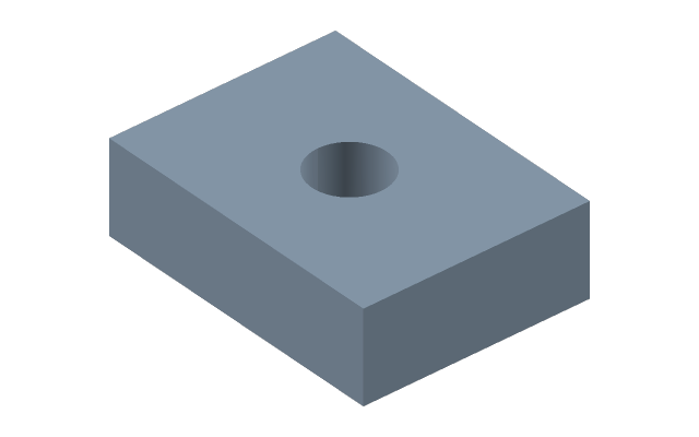
A hole keeps a reference to the face: change the part higher up the timeline and the hole stays where it was meant to be, not where the coordinates happened to land.
5. Fillets — and why they come last
Press F and click the four vertical edges. Type Radius 5 in the field at the geometry and
press Enter.

Fillets and chamfers go at the end: they add faces and edges, and what is built on those easily loses its footing when the shape changes. Shape first, then holes, then fillets.
6. And now the important part: change a dimension
Find the sketch in the tree on the left, open it with a double click, double-click the 40
dimension, type 60 and leave the sketch (Ctrl+Enter).
The part rebuilt as a whole: the plate got longer, the hole stayed on its face, the fillets on their edges. You redrew nothing.
That is what a parametric model is for: it stores not a shape but a recipe for a shape. The timeline on the left is that recipe, and it can be edited anywhere.
What next
- The second lesson: an assembly — how to put parts against each other.
- The Sketch section — every drawing tool and the constraints between them.
- The Part section — every construction command.
- Parameters and formulas — how to keep one number the whole part depends on.