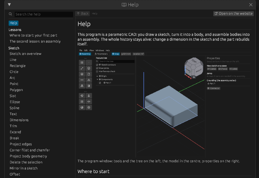
Help
This program is a parametric CAD: you draw a sketch, turn it into a body, and assemble bodies into an assembly. The whole history stays alive: change a dimension in the sketch and the part rebuilds itself.
Where to start
Start with the lessons — they are short and run in order, with no steps skipped:
- Your first part — sketch, dimensions, extrude, hole, fillet, and the important bit: change a dimension and watch the part rebuild itself.
- An assembly — components, joints, degrees of freedom.
What it is all made of
- Sketch — a flat drawing: lines, circles, arcs. All geometry stands on it.
- Part — turning a sketch into a body: extrude, revolve, sweep. The body is then refined with fillets, holes and shells.
- Assembly — several parts placed against each other by joints.
How the window is laid out
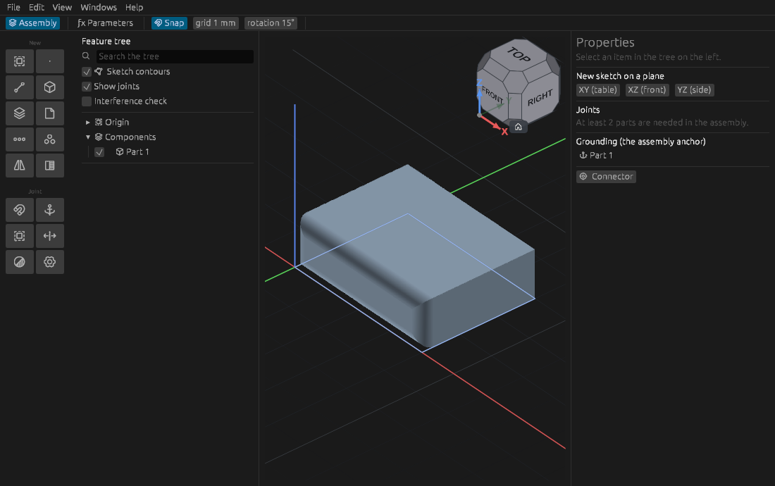
Tools of the current workbench are on the left. The document path and the bar with the modes of the active command are on top. Properties of the selection are on the right. The status line at the bottom says what is happening, how many degrees of freedom the sketch has and where the cursor is.
Rules shared by every tool
- A tool is a command: what is selected before it is taken at once, otherwise the tool waits for you to point; modes are in the bar on top, values in fields right at the geometry; the preview shows the result, Enter applies, Esc cancels.
- A double click on a timeline row reopens its command with the same fields.
- Every numeric field takes a formula:
40/2,len*2,sin(30)*10. Names come from the global parameters. - Nothing is applied on the fly: until you press Enter the document is unchanged.
Where to look next
- The program window — what lives where.
- The layout of the panels — where the panels stand, how to move and hide them, the buttons of the bar.
- Parameters and formulas — one number for the whole part.
- The history timeline and rollback — why a model is a recipe, not a picture.
- Keyboard shortcuts — the full reference and how to reassign them.
- Report a problem — something does not work: how to tell about it.
- Updates — how to learn about a new version, and what goes over the network.
F1 at any moment opens the article about what you are doing right now, not the contents page.