The viewport: looking and selecting
How to look
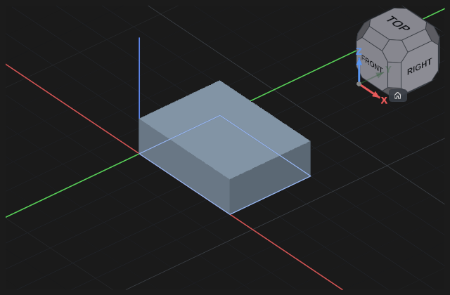
The view cube in the top right corner: click a face for the front, top or side view; a corner for an isometric one; an edge for a 45° view. The "home" button returns the isometric view. The view moves smoothly. The size of the cube is set in the settings.
Projection — orthographic or perspective, switched in the settings. Engineering work usually goes on in orthographic: equal sizes look equal there.
Moving the view with the mouse
The default layout is QymCAD:
- Dragging with any button turns the model. The left button turns it only when begun on the model; from empty space it draws a frame.
- Shift and drag moves the view sideways and up or down.
- In an assembly a part is carried without its gizmo with Shift and the left button, begun on the part. The middle and right buttons over a part move the view, as everywhere.
- The wheel zooms in and out towards the cursor: the point under it stays in place. In the settings, in the Zooming with the wheel row, you can choose "from the middle of the view".
- The view turns about the point of the model in the middle of the view, whatever distance it was zoomed from. Over empty space it is a point at the depth of the part seen nearest. In the settings, in the Turning the view about row, you can choose the point under the cursor. If a part has left the view, press the "home" button of the cube.
- While a command is open the view zooms about the centre of the part, so the command's fields do not slide away from under the hand. Pick "as usual" in the While a command is open row of the settings to turn that off.
Layouts of other programs
In the settings, in the Mouse navigation row, you can pick the layout of the program you are used to: CAD, Blender, Gesture, Maya, OpenCascade, OpenInventor, OpenSCAD, Revit, TinkerCAD or Touchpad. Each works as it does in its own program — under the name it says what its buttons do. How they differ:
- A middle click in CAD, Blender, Revit, OpenInventor, Maya and Gesture looks at the point under the cursor: it comes to the middle of the view, and the view turns about it from then on.
- Den is a layout for a pen: the left button turns the model, the middle one moves the view, the two together zoom in with a movement right or up and out with one left or down. In a sketch the left button stays the sketch's. Zoom and turn go about the point the view settings choose, as in the other layouts.
- The selection frame is drawn with Shift and the left button in Gesture, Maya and Den, there is none in OpenInventor and OpenSCAD, and the others draw it with the left button.
- Selecting in OpenInventor is a click with Ctrl or Shift: a bare left click there turns the model.
- Tilting the view exists only in Gesture — both buttons together. The view cube levels it again.
- In CAD a left click while the middle button is held turns the middle button to zoom for as long as it is held.
Selecting
- A click takes a face, an edge, a vertex or an outline; a double click takes the whole body; a click on empty space clears the selection. What will be taken is highlighted before the click.
- A frame takes the bodies (in an assembly, the parts) that fall wholly inside it.
- The right button on what is under the cursor offers "extend the selection" while a command that takes such a description is open.
In a sketch
A sketch is always flat: the view does not turn there under any layout.
- The middle button dragged moves the sheet. Under another layout the sheet moves with that layout's pan gesture. A two-button chord where one of them is the left one works too.
- The wheel zooms in and out by the same rule as in the 3D view.
- The left button belongs to the sketch under every layout: dragging a point, a line or a dimension moves it, from empty space it draws a frame. Ctrl or Shift with the left one adds to the selection.
If the model has gone out of sight, the "home" button on the view cube brings the isometric view back.
Section view
Click a plane or a face and half the model is hidden so you can look inside. This is only a view: the model is not cut and nothing goes into the export. The plane's shift and tilt are in the top bar.
What can be selected
A body, a face, an edge, a sketch outline, a component. Pointing precision is set in the settings — from “precise” to “coarse”: a touch screen and a 4K display need different hit radii.
Ghosts
A part outside the current context is shown semi-transparent — so that you can refer to it without it getting in the way. The transparency is set in the settings.
If the bodies are not drawn or the program closes at the start
The edges of a part are drawn and its faces are not, the picture breaks up, or the program closes without a word while its window opens - all of these come from the graphics card and its driver.
- Before the window opens, the program asks each graphics adapter to draw a test picture and takes the first one that draws. If an adapter draws only without antialiasing, the antialiasing is switched off for that start.
- If a start closes while the window is opening or in its first seconds, the next start draws more safely, one step at a time: without antialiasing, then through another graphics interface of the card, then on the processor. The status line says which, and a report of the start that closed is offered when the program opens.
- Settings -> Viewport, at the end of the section: Drawing with names the adapter in use. In Graphics adapter you can pick another one; it takes effect at the next start. After a safe start the button Draw as usual from the next start brings the usual drawing back.
If nothing helps, update the driver of the graphics card, and send the report with the problem (see Report a problem).